
A graph based analytical framework for resilient and energy aware sensor connectivity
Abstract
Self organizing wireless mesh networks enable sensing infrastructure to operate beyond the direct radio range of a gateway, but multi hop reachability alone does not establish system reliability. This study develops an analytical design framework for low power, predominantly gateway oriented mesh deployments. The framework separates physical connectivity from the active forwarding topology, evaluates route choice using delivery quality and resource constraints, and links fault recovery to energy depletion and aggregate traffic near gateways. We formulate a weighted parent selection criterion, a simplified end to end packet delivery model, and a radial traffic concentration model. Under an explicitly illustrative independent link assumption, ten hops with 0.97 per hop success yield 73.7% one attempt end to end success; this is a mathematical sensitivity example, not an observed deployment result. A uniform radial example also reveals that gateway adjacent forwarding nodes handle disproportionate traffic. The analysis motivates multi gateway placement, relay energy budgeting, conservative route switching, and evaluation of correlated failures. It concludes with a reproducible field validation protocol and the limits of the proposed approximations.
Keywords: wireless mesh network; self organization; multi hop routing; link quality; network resilience; energy hole; sensor network; gateway.
1 Introduction
Wireless sensor deployments increasingly require communication across large, obstructed or intermittently connected areas. Direct star connectivity can be attractive because it minimizes the forwarding workload of sensor devices, yet it becomes fragile when a node cannot reach its gateway. Wireless mesh networking addresses this limitation by allowing selected nodes to relay packets through neighboring devices. A mesh can therefore extend coverage and offer alternative routes, subject to the capacity and energy of its participating relays [1, 6].
A critical engineering distinction is that geometric connectivity and application level service are not equivalent. A network may show multiple radio neighbors while a routing algorithm selects only one usable parent per node, while relay queues become congested, or while repeated retries deplete a gateway adjacent battery. Network design must therefore account for routing state, link variability, packet age, channel occupancy and energy as coupled constraints. These issues are developed in the source technical study MESH2026, particularly in its routing, radio, area mesh and energy model sections [M].
The objective of this article is to provide a compact analytical method for designing and evaluating a self organizing, gateway oriented wireless mesh network. Three questions guide the analysis: (i) how should usable links and forwarding parents be selected; (ii) how does multi hop operation modify reliability and recovery; and (iii) where do forwarding demands create disproportionate energy costs? The contribution is a synthesis and a proposed evaluation workflow. No original experimental dataset is asserted.
2 Network Architecture and Related Protocols
2.1 Physical connectivity and forwarding topology
Let G = (V, E) represent the radio connectivity graph, where V is the set of devices and an edge (u, v) belongs to E when a measured link meets a stated operational acceptance rule. The existence of a link is not a binary property of distance alone: propagation losses, interference, packet length, modulation and receiver sensitivity all influence whether a usable connection exists. A forwarding topology F is a selected subset of E that defines where packets actually travel. A physical mesh can thus operate using a temporary tree or a directed acyclic graph (DAG) rooted at one or more gateways.
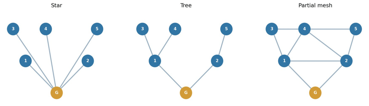
Figure 1. Conceptual star, tree and partial mesh radio topologies. Links depict connectivity rather than guaranteed delivery.
Figure 1 highlights the central trade off. A star reduces forwarding complexity but demands direct gateway reachability. A tree extends reach but makes a parent failure disruptive to all descendants. A partially meshed physical graph can provide standby paths, although redundancy helps only when the forwarding and recovery protocol can discover and exploit it. Full mesh connectivity is usually neither necessary nor practical for constrained radios because radio contention and state maintenance increase with the number of possible neighbors.
2.2 Proactive, reactive and hybrid route maintenance
Proactive protocols continuously maintain network reachability information and can deliver with little route discovery delay at the cost of periodic signaling. Reactive protocols such as AODV establish paths when required and use sequence numbers and route error processing to protect freshness, but route discovery adds startup latency [1, 71]. Hybrid approaches exploit both ideas. IEEE 802.11s specifies a mesh path selection framework with the Hybrid Wireless Mesh Protocol (HWMP), whose on demand and proactive components are described in the IEEE 802.11s literature included in the source bibliography [20, 29]. For constrained IPv6 networks, RPL organizes routing around destination oriented DAGs and rank constraints; related routing metrics are covered by RFC 6551 as cited in the source document [78, M].
Approach Operational advantage Main cost or limitation
Control traffic persists during idle Proactive Routes already available periods
Discovery latency and flood Reactive Lower idle control overhead management
Gateway oriented routes plus on More configuration and state Hybrid / rooted demand options interactions
Structured forwarding toward a Objective function must match Ranked DAG root application needs
Protocol names are not interchangeable implementations. The present framework intentionally defines generic functions – neighbor acceptance, parent ranking, fallback and telemetry – that must be mapped onto the selected radio stack and applicable standard.
3 Analytical Method
3.1 Link acceptance and parent selection
Each candidate link is characterized over an observation window by packet reception ratio (PRR), expected transmission count (ETX), latency, signal diagnostics and variability. For a directional link with measured success probability p > 0, an elementary approximation is ETX = 1/p; practical bidirectional estimates must also account for acknowledgement delivery and asymmetric links. RSSI alone is not an adequate acceptance criterion because it does not uniquely identify collision probability, interference or temporal loss bursts.
A proposed parent score for node i and neighbor j is J(i,j) = w₁·ETX(i,j) + w₂·L(j) + w₃·B(j) + w₄·Epen(j) + w₅·Q(j), where L is an estimated remaining path cost, B is normalized relay load, Epen penalizes low residual energy and Q represents queue delay or packet age. All terms must be normalized before weights are set. A parent is eligible only if its path to the gateway is valid and an acyclic ordering condition is satisfied. This weighted score is a design proposal, not a standard specific routing metric.
To prevent oscillations between similarly ranked parents, a node should switch only if the alternative is better by a defined margin for a minimum observation interval, or if the current path is unavailable. Hysteresis improves stability but may delay useful adaptation; both the margin and timer require measurement under the intended mobility and interference profile. An explicit backup parent can reduce outage time if periodic probes do not exceed the radio and battery budget.
3.2 Hop dependent delivery sensitivity
For a single transmission attempt across h hops, a highly simplified model assumes that every hop succeeds independently with identical probability p. In that case Pdelivery(h) = p^h. For nonidentical independent links, Pdelivery = ∏ᵢ pᵢ. Correlated interference, collisions and time varying losses violate the independence assumption. Link layer retries, selective acknowledgements and alternate paths can increase delivery but generate additional airtime, processing delay and energy expenditure. The model is therefore a sensitivity tool, not a network performance prediction.
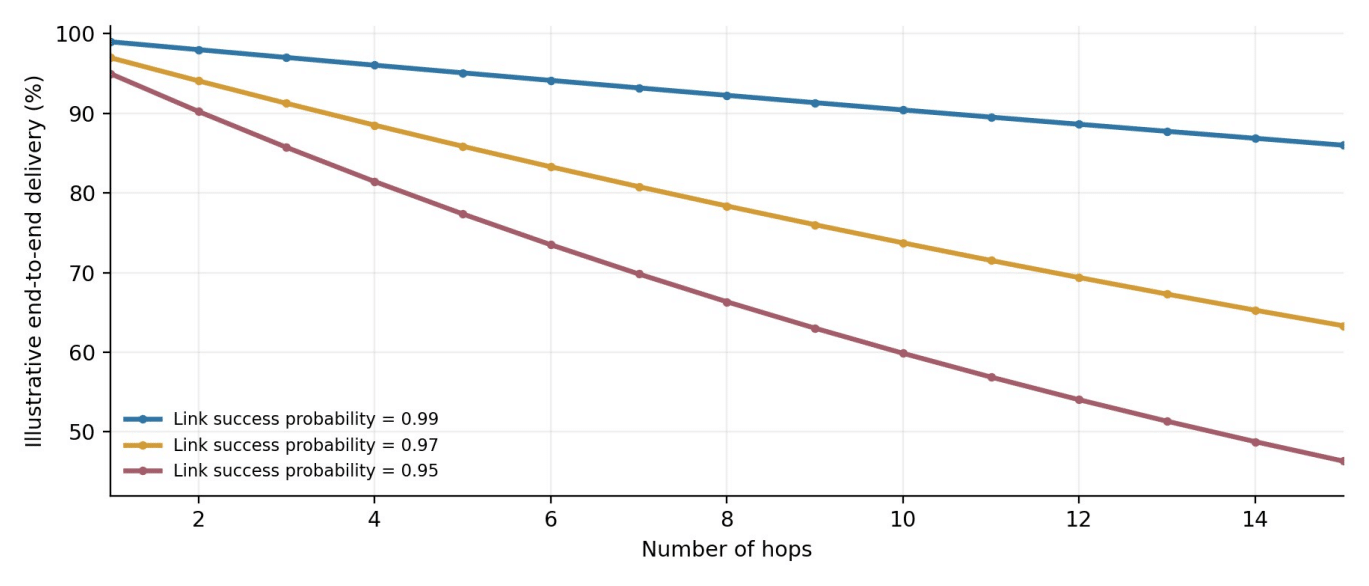
Figure 2. Calculated one attempt delivery probability versus hop count under independent, identical links; illustrative assumptions, not measurements.
For example, p = 0.97 and h = 10 yield 0.97^10 = 0.7374, or 73.7% nominal one attempt success. Raising per hop success to 0.99 produces 90.4% over the same distance. Thus apparently small differences in link quality become consequential in long forwarding chains. Conversely, this product should not be used to claim actual end to end packet delivery rate when a protocol includes retries or redundancy. Those behaviors must be modeled explicitly and tested.
3.3 Traffic concentration and energy holes
Consider a uniformly populated circular deployment divided into k = 1 … K radial rings of equal width Δ around a central gateway. Under uniform areal density ρ, the expected ring population is Nₖ ≈ πρΔ²(2k − 1). Suppose every node originates one packet in a reporting interval and all outward traffic crosses each inner ring exactly once. The aggregate number of packets traversing ring k is Tₖ = Σⱼ₌ₖᴷ Nⱼ. If forwarding is perfectly balanced among its Nₖ devices, the mean packets handled per device is approximately Tₖ/Nₖ; this counts the node’s own packet and forwarded traffic, but excludes retransmissions and receptions for overhead accounting.
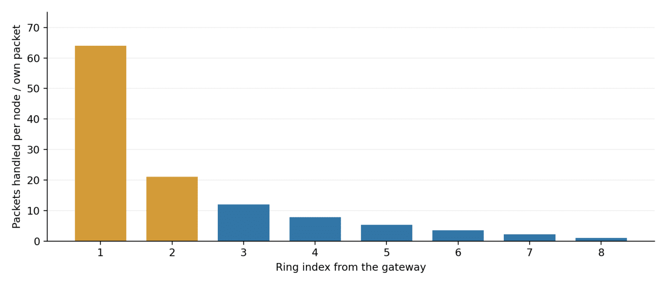
Figure 3. Analytically calculated forwarding burden in an eight ring uniform radial network, assuming one packet per node and ideal equal balancing. Not empirical data.
In this stylized eight ring network the innermost ring contains one relative population unit while 64 relative source units must cross it; the outermost ring handles only its own traffic. The magnitude is a deliberate geometric limiting case, not a predicted physical deployment ratio. Alternative path geometries, multiple gateways, unequal node density, duty cycling and in network data aggregation change the numerical outcome, but the direction of the bottleneck is robust: devices near a unique gateway often perform more relay work than distant leaves.
A first order node current model illustrates the coupling: Iavg,i ≈ Isleep + fmeas·Qmeas + fown·Qtx + λrelay,i·Qrelay + fctrl·Qctrl, with frequencies expressed in events per unit time and each Q as charge per event. Relay load λrelay,i depends on topology and traffic generation; frequent rerouting also increases fctrl. The duration estimate of a battery node is then L ≈ Ceff/Iavg,i when units are consistent. Temperature, self discharge, radio peaks and battery voltage cutoff require additional corrections [M].
4 Failure Recovery and Resilience
Self organization should be treated as a controlled sequence rather than an informal property. During initial joining, a device discovers neighbors, authenticates if required, evaluates link quality and selects a loop free route. During normal operation it samples health metrics and reports path information. A potential failure is detected through missing acknowledgements, probes or route error messages. The node then selects an eligible alternate parent, updates its forwarding state and verifies delivery restoration. If no route exists, it buffers messages only within an explicit storage and age limit. Such store and forward operation is particularly important in disrupted or intermittently connected deployments, including the DTN scenarios addressed in the source bibliography [82, 83].
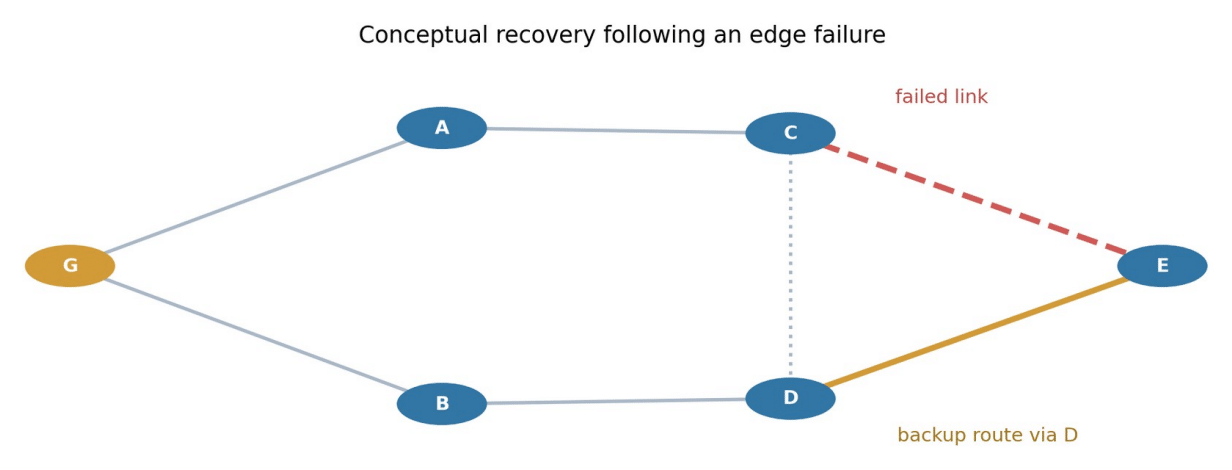
Figure 4. Example of a failed upper link and an alternate lower route. Schematic only; recovery time depends on implementation and traffic timing.
Network resilience must be quantified using more than whether a node eventually reconnects. At minimum, measurements should include outage duration, number of packets lost or delivered late, route convergence time, extra control traffic, additional current draw, and the effect on other users sharing the wireless channel. A backup path that restores reachability but causes overload near the gateway is not necessarily an acceptable recovery. Similarly, fast reassociation may have little practical value if low duty cycle schedules defer the next payload transmission for several minutes.
5 Optimization Strategy
5.1 Joint routing and gateway placement
The design objective is multi criteria: maximize usable coverage and timely delivery while limiting relay energy, congestion and operational complexity. A gateway placement candidate should be evaluated not only by maximum geometric distance but also by the number of hops to critical nodes, projected aggregate throughput through its adjacent relays, the capacity of the backhaul connection, and physical exposure to correlated radio disruption. Placing a second gateway can shorten route lengths and redistribute relay traffic, but it introduces coordination and gateway selection decisions. Where deployment budgets are tight, selective reinforcement of gateway adjacent relays may yield larger benefit than adding uniformly spaced leaf nodes.
5.2 Practical design constraints
Recommended measurable Design dimension Design response criterion
Bidirectional PRR and ETX Reject unstable parents; document Connectivity distributions antenna placement
Convergence time and backup path Maintain bounded alternate route Route resilience success information
Airtime occupancy, queue age and Bound reporting rate; distribute Congestion drops parent load
Charge per TX, RX, scan and Budget energy by relay role and Energy forwarding event temperature Timely application PDR at each hop Validate end to end with actual Reliability depth protocol retries
Join authentication and replay Protect identity and routing control Security handling traffic
Optimization should occur at multiple timescales. Radio acceptance and routing respond to link failures within operational limits. Reporting rate adapts to network congestion and urgency. Gateway positions, relay batteries and physical antenna arrangements are relatively slow design decisions. Mixing all adjustments without constraints can lead to persistent instability; thresholds, cooldown intervals and a defined safe fallback profile are necessary.
6 Evaluation Protocol for Field Validation
A publishable empirical extension should use predeclared hypotheses and repeated trials across controlled scenarios. The proposed protocol includes (a) a baseline direct or tree configuration, (b) a mesh configuration with route recovery enabled, (c) interference or deliberate relay outage tests, and (d) load tests with increasing reporting rates. Compare identical payload size, frequency band, transmit power, antenna placement and observation period wherever feasible. Randomize outage order and repeat each scenario sufficiently to describe variation, not only a single favorable example.
Metric Definition or procedure Reporting requirement
Unique messages received / Per node, hop depth, scenario and Application PDR messages originated confidence interval
Receive timestamp minus origin Median, p95 and time End to end latency timestamp synchronization method
Failure timestamp to first valid Recovery time Distribution across repeated outages restored route
Control frames and airtime per Control overhead By protocol mode and network size useful packet
Integrated current over Node charge Separate leaves and critical relays representative cycles
Distinguish forced from Route stability Parent changes per node-hour unnecessary changes
The study should archive radio settings, network firmware revisions, gateway count, terrain or obstruction notes, topology snapshots and raw packet logs. For a fair resilience comparison, failures must affect equivalent nodes; otherwise the experiment confounds protocol behavior with physical topology. The trial should report failed runs as well as successful ones and avoid pooling different hop depths without stratification. These measures are a proposed validation procedure informed by the network design surveys already listed in MESH2026 [2, 71].
7 Discussion and Limitations
The framework indicates that optimization of a mesh cannot be reduced to increasing the number of neighbors. More candidate links provide optionality, but every connection also has an observation and coordination cost. In gateway centric traffic, the dominant failure mechanism can shift from absent long range coverage to overloaded or exhausted inner relays. Both effects grow in relevance as hop count and reporting intensity rise. This explains why route quality, energy state and congestion should be treated jointly in parent selection rather than as unrelated tuning steps.
Several limits prevent quantitative generalization. The probability calculation assumes independent one attempt links, whereas real radio errors may be temporally and spatially correlated. The radial model assumes uniform node density, balanced forwarding, a single central gateway, no traffic aggregation and no protocol overhead. The weighted parent score contains parameters that cannot responsibly be fixed without actual measurements. Furthermore, different media access schemes have distinct collision and scheduling costs. Consequently, the figures demonstrate mechanisms and sensitivity; they do not validate a specific commercial product, network capacity or lifetime.
This study concentrates on low data rate sensor messages directed toward gateways. It does not establish performance for high throughput peer to peer traffic, video, highly mobile swarms, or a specific LoRa MESH implementation. Security, interoperability and ruggedization remain essential deployment conditions, but a substantive assessment of them requires dedicated analysis.
8 Conclusion
A self organizing wireless mesh can increase usable sensing coverage and preserve paths after selected failures, but successful operation depends on simultaneous control of routing, radio reliability, delay and relay energy. The proposed graph based methodology explicitly distinguishes possible radio links from active routes, ranks candidate parents using path and resource costs, and demonstrates the compounding effect of imperfect hops. An analytical radial model further identifies a structurally important gateway adjacent relay burden. The immediate design implication is to establish application specific service thresholds and measure them across hop depth and failure scenarios before fixing gateway placement, parent scoring weights or battery sizing. Future work should validate recovery and traffic models using synchronized packet logs, power traces and repeated field experiments.
References
[1] A. Cilfone, L. Davoli, L. Belli, and G. Ferrari, “Wireless Mesh Networking: An IoT-Oriented Perspective Survey on Relevant Technologies,” Future Internet, 11(4), 99, 2019. DOI: 10.3390/fi11040099.
[2] D. Benyamina, A. Hafid, and M. Gendreau, “Wireless mesh networks design—A survey,” IEEE Communications Surveys & Tutorials, 14(2), 299–310, 2012. DOI: 10.1109/SURV.2011.042711.00007.
[6] I. F. Akyildiz, X. Wang, and W. Wang, “Wireless mesh networks: a survey,” Computer Networks, 47(4), 445–487, 2005. DOI: 10.1016/j.comnet.2004.12.001.
[20] X. Wang and A. O. Lim, “IEEE 802.11s wireless mesh networks: Framework and challenges,” Ad Hoc Networks, 6(6), 970–984, 2008. DOI: 10.1016/j.adhoc.2007.09.003.
[29] G. R. Hiertz et al., “IEEE 802.11s: The WLAN Mesh Standard,” IEEE Wireless Communications, 17(1), 104–111, 2010. DOI: 10.1109/MWC.2010.5416357.
[71] D. Rodenas-Herraiz et al., “Current Trends in Wireless Mesh Sensor Networks: A Review of Competing Approaches,” Sensors, 13(5), 5958–5995, 2013. DOI: 10.3390/s130505958.
[78] J.-P. Vasseur et al., “Routing Metrics Used for Path Calculation in Low-Power and Lossy Networks,” RFC 6551, 2012. DOI: 10.17487/RFC6551.
[82] V. Cerf et al., “Delay-Tolerant Networking Architecture,” RFC 4838, 2007. DOI: 10.17487/RFC4838.
[83] S. Burleigh, K. Fall, and E. Birrane, “Bundle Protocol Version 7,” RFC 9171, 2022. DOI: 10.17487/RFC9171.
[M] MESH2026-v07. Technical study, sections 3.1, 3.3–3.5 and 4.1–4.3. Unpublished technical material.
Pridaj komentár